
- All
- Product Name
- Product Keyword
- Product Model
- Product Summary
- Product Description
- Multi Field Search
Please Choose Your Language
Views: 0 Author: Site Editor Publish Time: 2026-07-13 Origin: Site


Material failure in production or field applications often traces back to improper metallurgical verification, incorrect heat treatment, and surface integrity failures. Selecting the wrong testing methodology or misunderstanding the mechanical limitations of a specific Hardness Testing Machine leads to invalid data, non-compliance with industry standards like ASTM or ISO, and costly production bottlenecks.
To make an informed procurement decision, quality assurance, metallurgy, and engineering teams must understand the underlying mechanics of indentation, load application, and optical measurement. This guide breaks down the operational principles of industrial hardness testers, compares standard methodologies, and provides a clear framework for evaluating which system aligns with your specific material and compliance requirements.
A hardness testing machine operates by applying a controlled force through a specific indenter (diamond, tungsten carbide ball, or spring-loaded pin) to measure a material's resistance to permanent plastic deformation or elastic indentation.
The choice of testing method—whether measuring penetration depth (Rockwell) or optical indentation size (Vickers/Brinell)—must dictate the machine's mechanical, optical, and software architecture.
Modern closed-loop load cell systems offer significant advantages over traditional deadweight machines by eliminating mechanical friction, weight-stack drift, and operator-induced load application errors.
Selecting the right equipment requires balancing material class (metals vs. polymers), sample geometry, required test scales, ASTM/ISO compliance needs, and the testing environment (laboratory vs. shop floor).
The fundamental principle of hardness testing revolves around indentation and permanent deformation. A testing unit presses a harder material, known as the indenter, into the test specimen under highly controlled conditions. By measuring the resulting deformation—either the depth of penetration or the surface area of the indentation—the system calculates a specific hardness value. This process requires exact control over the applied force and precise measurement mechanisms to ensure repeatability across multiple shifts and operators.
Traditional deadweight systems rely on physical weights, pivot levers, and dashpots to apply force. While historically reliable in controlled environments, these mechanical setups remain susceptible to environmental vibration, friction, and mechanical wear over time. Weight stacks can drift out of calibration, and mechanical linkages introduce inconsistencies during load application, especially if the dashpot oil degrades or temperature fluctuates.
Modern closed-loop electromechanical systems replace physical weights with electronic load cells, piezo-actuators, and continuous force feedback loops. These systems apply, maintain, and remove force with high precision. By continuously monitoring the applied load at a rate of hundreds of times per second, closed-loop systems eliminate overshoot and significantly improve repeatability. They ensure accurate results regardless of operator influence, minor mechanical wear, or external vibrations.
Feature | Traditional Deadweight Systems | Closed-Loop Electromechanical Systems |
|---|---|---|
Force Application | Physical weights, levers, and dashpots | Electronic load cells and continuous feedback |
Accuracy & Repeatability | Moderate; degrades with mechanical wear | High; continuous monitoring prevents overshoot |
Maintenance Needs | High; requires regular cleaning and oil checks | Low; fewer moving parts and no oil dashpots |
Vibration Sensitivity | High; external shocks affect the weight stack | Low; active feedback compensates for minor shocks |
Once the indentation occurs, the machine must translate physical deformation into quantifiable data. The method depends entirely on the testing scale being used and the physical properties of the material under evaluation.
Depth-measurement sensors are primarily used in Rockwell testing. These systems utilize Linear Variable Differential Transformers (LVDTs) or high-resolution optical encoders to measure penetration depth down to sub-micron levels. The machine calculates hardness based directly on this depth differential, requiring no optical intervention from the operator.
Optical imaging systems are essential for methods that evaluate the surface area of the indentation. A Vickers hardness tester or a Brinell system relies on high-resolution optical microscopes, motorized turret systems, and digital image analysis software. These components work together to accurately measure the diagonals or diameter of the indentation. The software then converts these physical dimensions into a standardized hardness value based on established mathematical formulas.
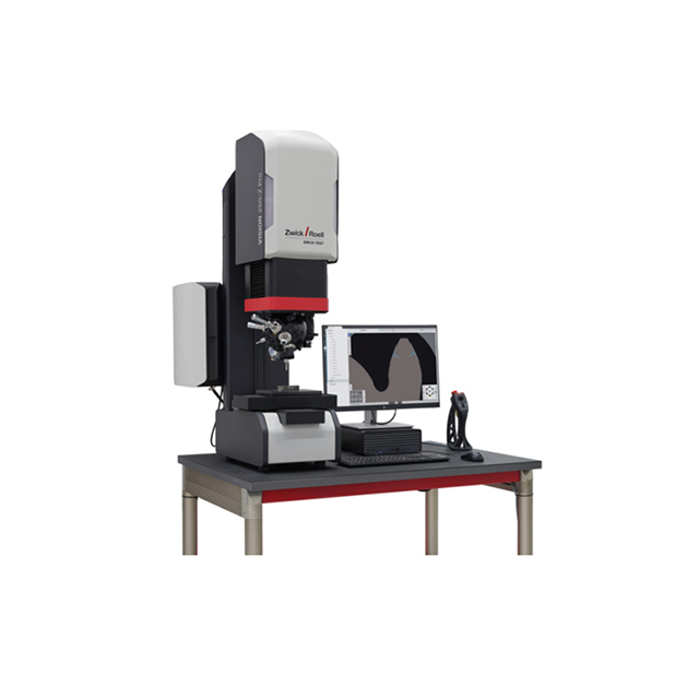
Rockwell testing relies on a two-step load process. The machine first applies a minor load, or preload, to break through surface contamination and establish a zero reference position. It then applies the major load to create the main indentation. Finally, the system returns to the minor load to measure the net residual depth of penetration. This depth directly correlates to the Rockwell hardness number, providing an immediate readout.
Standard Rockwell testing operates at major loads of 60, 100, and 150 kgf, making it suitable for bulk structural materials like carbon steel, titanium alloys, and thick aluminum plates. Superficial Rockwell testing uses lower loads of 15, 30, and 45 kgf. This superficial method is designed for thin sheet metal, case-hardened surface layers, and components where deep indentation must be avoided to prevent structural damage or punch-through.
Common indenters include the 120° spheroconical diamond Brale indenter and tungsten carbide balls ranging from 1/16" to 1/2" in diameter. These correspond to various scales, such as HRC, HRB, and HR15N. Because Rockwell provides direct readouts without requiring optical measurement steps, it is the preferred method for high-speed, high-volume quality control on production floors.
The Vickers method uses a square-based diamond pyramid indenter with an angle of 136° between opposite faces. When pressed into the material, it produces a distinct square indentation. The operating principle relies entirely on optical evaluation rather than depth measurement, requiring a highly polished surface finish to ensure the corners of the indentation are visible.
After indentation, the operator or automated system measures both diagonals of the resulting square using an optical microscope. The average of these two diagonals is used to calculate the Vickers Pyramid Number (HV). Modern systems utilize digital cameras and image analysis software to perform this measurement automatically, reducing operator error and speeding up the testing cycle.
The primary engineering benefit of the Vickers method is its single continuous scale across all material hardnesses. The same indenter geometry applies to very soft lead and extremely hard tungsten carbide. This versatility makes it the industry standard for testing thin films, coatings, case-hardened depth profiles, and weld heat-affected zones (HAZ) where hardness gradients change rapidly over short distances.
Brinell testing utilizes high-force mechanics to evaluate materials. The method employs a large tungsten carbide ball indenter, typically 1mm, 2.5mm, 5mm, or 10mm in diameter, and applies high loads ranging from 156.25 kgf up to 3000 kgf. Like Vickers, Brinell relies on optical measurement, evaluating the diameter of the resulting circular indentation using a specialized microscope or digital scanner.
This heavy-duty mechanical approach is necessary for materials with coarse or non-uniform grain structures. When testing cast irons, large forgings, and structural steel, a small indentation might hit a single hard carbide phase or a soft graphite flake, giving a false reading. The large Brinell indentation averages out these micro-structural inconsistencies, providing a reliable representation of the bulk material hardness.
Microhardness testing applies extremely low loads, typically ranging from 1g to 1000g (10N), to evaluate specific microstructures, thin wires, or foil cross-sections. This requires highly sensitive load application and precise optical measurement, often utilizing objectives with 40x or 50x magnification.
While low-load Vickers is common, the Knoop method utilizes an elongated, asymmetrical diamond pyramid indenter. This geometry produces a shallow penetration and an elongated horizontal diagonal. The Knoop profile minimizes cracking in highly brittle materials like ceramics, glass, and thin coatings, making it ideal for these specific applications where a standard Vickers diamond might shatter the sample.
Due to the extremely low forces involved, microhardness testing faces strict environmental constraints. Mechanical necessities include vibration isolation tables, draft shields, and high-magnification objectives. Even minor external vibrations from a nearby forklift or HVAC system can alter the indentation size and invalidate the test results.
Shore testing evaluates non-metallic materials, including plastics, rubbers, elastomers, and soft polymers. Unlike methods for metals, Shore testing relies on spring-loaded indentation rather than deadweights or load cells.
A Shore durometer utilizes a calibrated spring to press a hardened steel rod, either a pin or a cone, into the specimen. The device measures the resistance depth. Crucially, this method evaluates the material without inducing permanent plastic deformation, which is necessary for viscoelastic materials that recover their shape after the load is removed. Different scales, such as Shore A, D, and M, use varying spring forces and indenter geometries to cover different polymer hardness ranges.
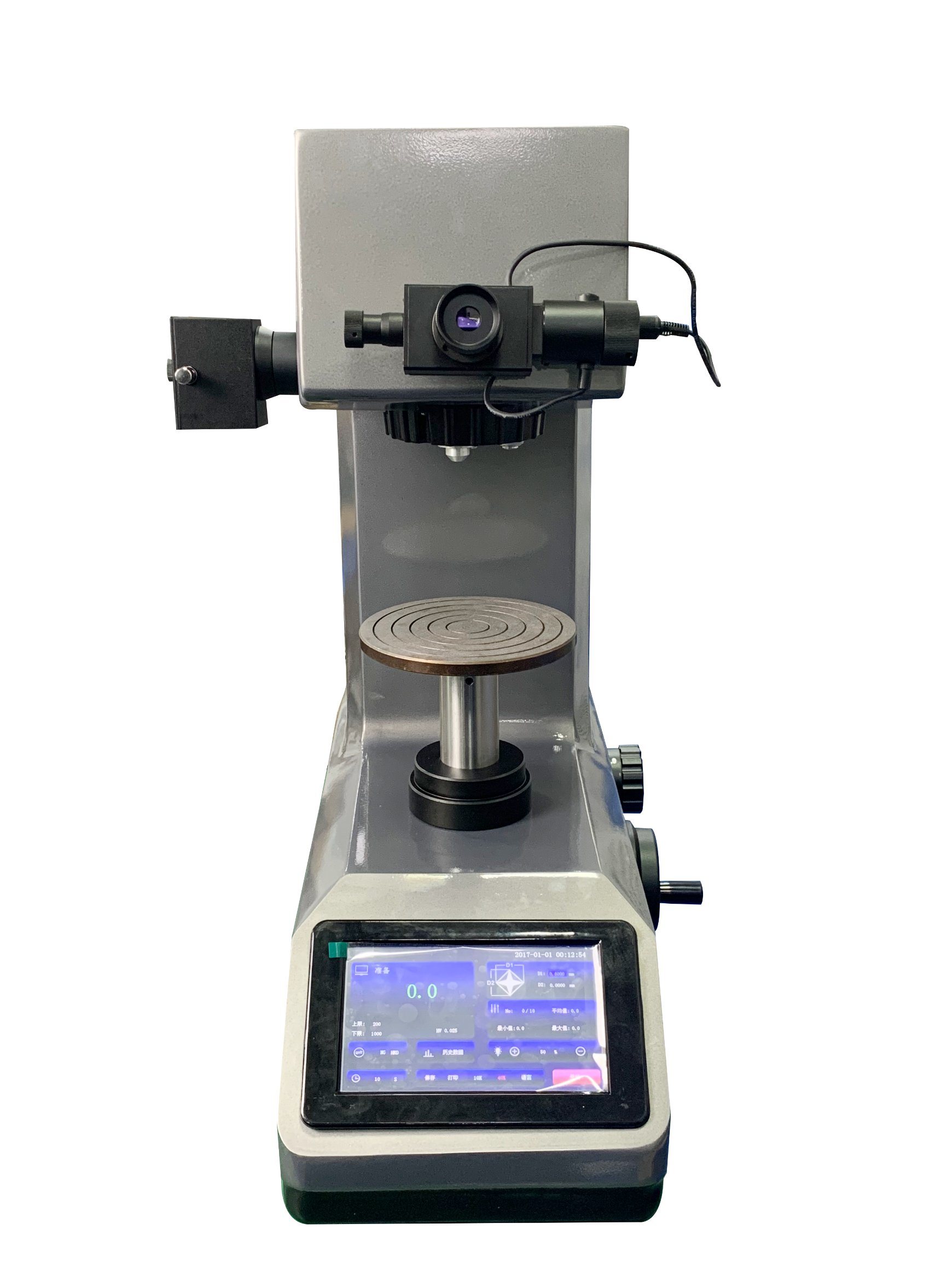
Benchtop hardness testing machines provide lab-grade accuracy primarily due to their structural rigidity. These systems feature heavy-duty cast-iron or C-frames designed to prevent frame deflection during high-load application. Maintaining perfect perpendicularity between the indenter and the specimen is critical for accurate results; even a one-degree tilt can skew a Rockwell depth reading.
These robust frames are the standard for certified laboratory environments. They ensure strict compliance with international testing standards, including ASTM E18, ASTM E92, ASTM E10, and ISO 6506/6507/6508. When absolute precision, verifiable traceability, and third-party audit compliance are required, a benchtop system is mandatory.
Portable hardness testers allow for on-site integrity verification of large components like pipelines, pressure vessels, and massive castings that cannot be moved to a laboratory. These devices use different mechanical principles to estimate hardness.
The Leeb rebound method uses spring force to propel an impact body against the test surface. The device measures the ratio of rebound velocity to impact velocity, converting this dynamic energy loss into a hardness value. It requires a massive, rigid test piece to prevent the part itself from absorbing the impact energy.
The Ultrasonic Contact Impedance (UCI) method utilizes a Vickers diamond mounted on an oscillating rod. When pressed into a material, the contact area dampens the oscillation. The device measures this frequency shift and calibrates it to a hardness value. UCI is better suited for lighter parts and heat-affected zones than Leeb testing.
Shear-pin and reference-bar methods, such as the Telebrineller, use a classic mechanical comparison. A hammer blow transfers force through a reference bar of known hardness to a steel ball. Users then compare the resulting indentation diameters on the reference bar and the specimen to determine hardness.
While portable testers offer convenience, they come with trade-offs. They cannot match lab accuracy and have strict requirements for specimen thickness, mass, and surface preparation. Furthermore, they often rely on indirect conversion tables to estimate standard scales like Rockwell or Brinell, which can introduce significant error margins depending on the material's elastic modulus.
Selecting the correct machine requires matching the testing method to the specific material class. For example, you should avoid Brinell testing for ultra-hard carbides, as it can deform or shatter the tungsten carbide ball indenter. High-load Rockwell testing is unsuitable for delicate micro-components, which require microhardness methods to prevent crushing the part. Shore testing is specifically designed for polyurethanes and elastomers, offering no value for metallic alloys.
Material grain structure also dictates selection. When dealing with multi-phase alloys or materials with coarse anisotropy, macro-Vickers or Brinell methods are necessary to average out the structure. Micro-Knoop testing on a coarse-grained cast iron would yield highly variable results depending on which specific grain or phase the indenter hits.
Physical envelope constraints limit which machine you can use. You must consider the vertical daylight capacity and throat depth of the tester to ensure your largest parts will fit within the testing area. Cylindrical or irregular parts require specialized self-centering v-anvils, clamping caps, or custom fixtures to maintain stability during testing. If a cylindrical part rolls even slightly during load application, the test is invalid.
Surface preparation thresholds heavily influence method selection. Methods relying on optical measurement, like Vickers and microhardness, require highly polished, mirror-like surfaces (often requiring metallographic preparation) to accurately read the small indentations. Rockwell testing, which measures depth, is far more tolerant of rougher surface finishes, making it better suited for raw or minimally processed parts straight off the lathe or mill.

To ensure accurate material verification and equipment selection, implement these next steps:
Audit your current material testing requirements against specific ASTM and ISO standards to identify the exact testing scales required for compliance.
Evaluate your typical sample geometries, including maximum height and weight, to determine the required machine throat depth and anvil configurations.
Assess your testing environment to decide if a rugged closed-loop benchtop system for the lab or a portable unit for the shop floor best fits your workflow.
Establish strict surface preparation protocols based on whether you utilize depth-measurement (Rockwell) or optical evaluation methods (Vickers/Brinell).
A: Rockwell testing measures the depth of penetration using a two-step load process and provides a direct hardness readout without optical intervention. Vickers testing relies on the optical measurement of the diagonals of a square indentation left by a diamond pyramid indenter, requiring a polished surface.
A: Closed-loop systems use electronic force feedback to apply loads with high precision. This eliminates mechanical friction, vibration sensitivity, and weight-stack drift common in traditional deadweight machines, resulting in better repeatability and less maintenance.
A: Generally, no. Portable testers are excellent for on-site verification but rely on indirect conversions and dynamic methods. Certified lab results typically require rigid benchtop systems that comply strictly with ASTM or ISO standards to ensure traceability.
A: Microhardness testing requires a highly polished, mirror-like surface finish, often achieved through metallographic grinding and polishing. Because the indentations are extremely small, any surface scratches or roughness will obscure the optical measurement of the indentation diagonals.
A: Brinell testing is ideal for materials with coarse or inhomogeneous grain structures, such as cast iron or large forgings. The large ball indenter and high load create a macro-indentation that averages out micro-structural inconsistencies, providing a reliable bulk hardness reading.


