
- All
- Product Name
- Product Keyword
- Product Model
- Product Summary
- Product Description
- Multi Field Search
Please Choose Your Language
Views: 0 Author: Site Editor Publish Time: 2026-07-16 Origin: Site


Material failure due to improper hardness verification introduces severe operational and financial risks across manufacturing, aerospace, and quality assurance sectors. When components fail under stress because their hardness was incorrectly assessed, the consequences range from catastrophic structural collapses to costly product recalls. Selecting the wrong indentation method or testing equipment directly causes bottlenecked QA workflows, inaccurate metallurgical data, scrap parts, and excessive sample preparation costs. Relying on an inappropriate testing strategy compromises the integrity of the entire production line.
Specifying the correct Hardness Testing Machine requires a rigorous understanding of mechanical differences, material constraints, operational costs, and trade-offs between the Rockwell, Vickers, and Brinell methods. Each technique serves distinct metallurgical requirements and production environments. Understanding these core differences ensures that quality control processes remain efficient, accurate, and compliant with industry standards.
Rockwell: Prioritizes cycle speed, low cost per test, and requires minimal surface preparation, measuring hardness via indentation depth. Ideal for rapid, high-throughput production environments.
Brinell: Utilizes a large indenter and high loads to measure indentation width. Best suited for rough, non-homogeneous materials like heavy castings, forgings, and raw structural alloys, though it leaves a highly visible, potentially destructive mark.
Vickers: Offers extreme precision using a diamond pyramid indenter to measure indentation width. Essential for micro-hardness testing, heat-treated case depths, thin films, and highly polished laboratory samples.
Equipment Strategy: Procurement decisions must weigh dedicated single-method machines against a universal hardness tester based on facility throughput, operator expertise, budget limits, and ASTM/ISO compliance requirements.
Hardness testing is not an absolute material property. It is an empirical measurement indicating a material's resistance to localized plastic deformation. Reliable QA data depends on selecting the appropriate testing method for the specific material and application. Establishing baseline criteria ensures that the resulting hardness values accurately reflect the material's structural integrity and suitability for its intended use. You must define what success looks like for your specific production line before selecting equipment. If you are testing engine blocks, your criteria will differ vastly from someone testing micro-electronics.
Engineers often mistake hardness for yield strength. While they correlate, hardness specifically measures surface resistance to indentation. When you set up a testing protocol, you need to account for surface finish, material thickness, and the homogeneity of the microstructure. Ignoring these factors leads to false passes and field failures. We see this frequently when shops try to use a single method for every part that comes through the door.
Hardness evaluation relies on two primary measurement philosophies. The Rockwell method uses depth-based measurement, calculating hardness from the differential depth of penetration under varying loads. Conversely, the Brinell and Vickers methods measure the optically determined area or width of deformation left by the indenter. These distinct mechanical approaches dictate the equipment required and the types of materials each method can accurately assess.
Depth measurement systems are inherently faster because they do not require optical analysis. The machine simply reads the linear displacement of the indenter. Optical systems, however, provide a physical impression that can be re-measured later if a dispute arises. This fundamental difference in mechanics drives the entire workflow of a quality control lab.
The size of the indentation directly affects part reusability. Vickers micro-indentation is generally the least destructive, leaving a microscopic mark suitable for finished components. The Rockwell minor-depth mark is also considered largely non-destructive for many applications. The Brinell method ranks as the most destructive, leaving a large, highly visible impression that often relegates the tested sample to scrap or requires subsequent machining.
When dealing with finished aerospace components, any surface marring can act as a stress riser. In these cases, you must use micro-indentation methods. For raw castings, a massive Brinell indent is irrelevant because the part will undergo heavy machining anyway. Understanding this scale helps you avoid scrapping perfectly good parts.
Rockwell testing offers rapid, direct-reading results, significantly reducing cycle times and labor costs. In contrast, Brinell and Vickers testing require optical alignment and precise measurement of the indentation dimensions. These additional steps increase the time per test and often demand skilled operators, mapping directly to higher overall laboratory labor costs compared to the automated efficiency of the Rockwell method.
Let us look at a practical breakdown of testing speeds. A standard Rockwell test takes about 5 to 10 seconds from start to finish. A manual Vickers test, including surface preparation and optical measurement, can take upwards of 5 to 10 minutes per sample. When you multiply that by hundreds of parts per shift, the labor economics heavily favor depth-based testing whenever the material allows for it.
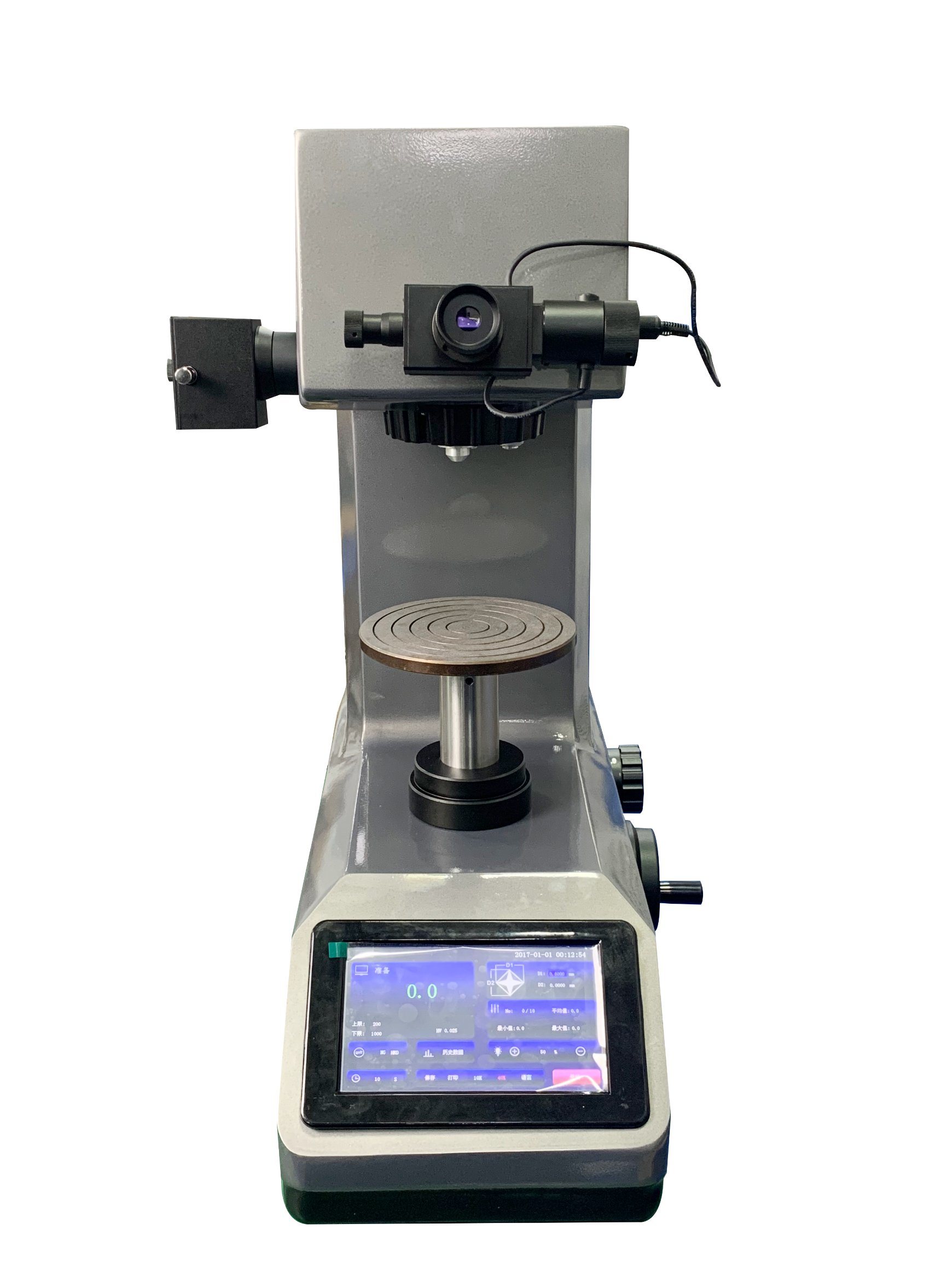
The Rockwell method employs a dual-load system. A minor pre-load establishes a zero reference position, penetrating the surface to eliminate effects from minor surface imperfections. A major load is then applied and subsequently removed, leaving the minor load engaged. The machine calculates the hardness value based on the permanent increase in depth of penetration. This direct depth measurement eliminates the need for optical evaluation.
This dual-load approach is brilliant for shop floor environments. The minor load effectively punches through light surface contamination or microscopic roughness, seating the indenter firmly in the actual material. This is why Rockwell is so forgiving compared to optical methods. The machine does the math internally, displaying a direct number on the screen.
Rockwell testing excels in evaluating heat-treated steels, copper alloys, and finished components. It is the preferred method when rapid testing cycle times and minimal surface marring are essential. Because it requires virtually no sample preparation, it integrates seamlessly into fast-paced production lines where immediate verification of heat treatment processes or material strength is required.
We use Rockwell extensively for checking case-hardened shafts and gears. As long as the case depth is sufficient to support the major load without yielding the softer core, the readings are highly reliable. It is also the go-to method for incoming raw bar stock verification.
Automated depth-reading systems and digital readouts provide significant value by eliminating human optical measurement errors and accelerating cycle times. The economic advantage of zero sample preparation makes these machines highly scalable for inline production environments. However, the method is sensitive to anvil misalignment, specimen curvature, and surface scale, which can skew the depth measurement and produce inaccurate readings.
When specifying a machine, pay close attention to the clamping mechanism. If the part shifts even a fraction of a micron during the application of the major load, the depth reading will be ruined. Modern machines use closed-loop load cells instead of dead weights, which provides much better control over the force application curve and reduces overshoot errors.
Ensure the anvil perfectly matches the geometry of the part being tested.
Verify that the minor load is applied smoothly without impact.
Check the calibration block daily before running production parts.
Keep the elevating screw clean and well-lubricated to prevent binding.
The Brinell test utilizes a large tungsten carbide ball indenter, typically ranging from 1mm to 10mm in diameter. It applies heavy loads, often up to 3000 kgf, to create a wide impression on the material surface. The diameter of this impression is then optically measured using a specialized microscope or an automated digital camera system to calculate the Brinell hardness number.
The sheer force involved in a Brinell test requires a massive, rigid frame. You are physically crushing a 10mm carbide ball into solid steel. The resulting crater is then measured across two perpendicular diameters, and the average is used to calculate the hardness. This method has remained largely unchanged for over a century because it works exceptionally well for heavy industry.
The large indentation area is critical for averaging out metallurgical inconsistencies found in rough materials, heavy forgings, and porous castings. By testing a larger surface area, the Brinell method provides a more representative hardness value for non-homogeneous microstructures, where a smaller indenter might hit an isolated hard or soft spot, yielding misleading data.
Consider a cast iron engine block. Cast iron is full of graphite flakes. If you use a micro-indenter, you might hit a flake and get a reading of near zero, or hit the matrix and get a high reading. The 10mm Brinell ball covers enough area to average out these microstructural variations, giving you the true bulk hardness of the casting.
High-rigidity, heavy-duty frames are necessary to handle massive test loads without deflection, ensuring accurate force application. While the testing cycle is slower, integrated optical measurement systems are required to accurately read the indentation diameter. Brinell's unique ability to test rough, unpolished surfaces where other methods fail saves significant labor on surface preparation, offsetting the slower test cycle.
Modern Brinell systems have largely replaced manual microscopes with optical scanning cameras. The operator simply places the camera over the indent, and the software automatically detects the edges and calculates the diameter. This removes the subjective human element from the measurement process and speeds up the workflow considerably.
Testing Method | Indenter Type | Measurement Principle | Best For |
|---|---|---|---|
Rockwell | Diamond Cone or Steel Ball | Depth of Penetration | High-volume production, heat-treated steel |
Brinell | Tungsten Carbide Ball (1-10mm) | Width of Impression (Optical) | Castings, forgings, rough surfaces |
Vickers | Diamond Pyramid | Width of Impression (Optical) | Micro-hardness, thin films, case depths |

Vickers testing applies a square-based diamond pyramid indenter to the material surface. The resulting diagonals of the impression are optically measured to determine the hardness value. A key advantage is that the Vickers scale is continuous across all load ranges, from micro-gram forces used on delicate samples to macro-force loads applied to robust components, using the same indenter geometry.
Because the geometry of the diamond pyramid remains constant regardless of the load, a Vickers hardness value of 500 HV is the same whether it was tested at 10 grams or 10 kilograms. This continuity makes it an incredibly powerful tool for research and development, allowing engineers to compare the hardness of microscopic coatings directly against bulk materials.
This method is essential for micro-hardness applications, case depth profiling, and evaluating thin coatings or foil materials. It is also highly effective for testing extremely hard materials, such as advanced ceramics and carbides. The precision of the Vickers method makes it indispensable for detailed metallurgical research and quality assurance of intricate or surface-treated parts.
When we need to determine the exact depth of a carburized layer on a gear tooth, we section the gear, polish it to a mirror finish, and run a Vickers micro-hardness traverse from the edge to the core. By plotting the hardness values at specific intervals, we can pinpoint exactly where the case ends and the core begins.
High-resolution optics, motorized turrets, variable load cell technology, and vibration-isolated tables are critical features for accurate Vickers testing. The primary implementation risk involves the strict requirement for mirror-finish surface preparation through grinding and polishing. Failure to eliminate surface scratches renders the optical data unusable, as the indentation diagonals cannot be accurately measured.
Vickers machines are highly sensitive instruments. Even the vibration from a forklift driving past the lab can distort a micro-indentation while the load is being applied. Therefore, heavy granite tables and active vibration dampening systems are standard requirements. The software must also be capable of auto-focusing and auto-measuring to reduce operator fatigue.
Section the sample using a precision wet saw to avoid heat damage.
Mount the sample in an epoxy or acrylic resin puck.
Grind the surface using progressively finer silicon carbide papers.
Polish the surface using diamond suspension down to 1 micron.
Ensure the testing table is completely isolated from floor vibrations.

A universal hardness tester represents a highly versatile hybrid solution. These advanced systems are capable of performing Rockwell, Vickers, and Brinell tests within a single testing frame. By integrating interchangeable indenters, multi-range load cells, and sophisticated optical analysis systems, they offer comprehensive hardness evaluation capabilities without requiring multiple dedicated machines.
These machines utilize advanced closed-loop force feedback systems to apply loads ranging from a few grams up to 3000 kilograms. The motorized turret automatically rotates between different indenters and objective lenses depending on the selected test method. This level of automation reduces setup time and minimizes the risk of operator error when switching between testing standards.
Investing in a universal system provides a clear return on investment for contract testing labs, aerospace QA departments, and academic R&D facilities. These environments frequently deal with highly diverse material streams requiring different testing methodologies. Consolidating capabilities into one machine maximizes testing flexibility and ensures readiness for varied quality control demands.
If your facility only tests one type of part all day, a dedicated machine is better. However, if you are a job shop that might test a massive iron casting in the morning and a delicate titanium aerospace fastener in the afternoon, a universal frame is the only logical choice. It prevents you from having to turn away work due to equipment limitations.
Procurement must compare the higher initial capital expenditure and complex multi-point calibration requirements of a universal system against the combined floor space, maintenance schedules, and software overhead of owning multiple dedicated machines. While the upfront cost is higher, the long-term versatility and space savings often justify the investment for facilities with diverse testing needs.
You also have to consider operator training. A universal machine has more complex software because it has to handle multiple testing standards. Operators need to understand the nuances of all three methods to use the machine effectively. Calibration is also more involved, as the technician must verify the load cells and optics across a massive range of forces and magnifications.
Labor hours and training costs associated with sample preparation heavily influence equipment selection. Vickers testing requires meticulous grinding and polishing, increasing labor costs per test. Conversely, the rapid, near-zero-prep cycle times of automated Rockwell testing significantly reduce labor economics, making it preferable for high-volume production environments where throughput is paramount.
Do not underestimate the cost of consumables. Polishing pads, diamond suspensions, and mounting resins add up quickly. If you can get away with a Rockwell test on a ground surface instead of a Vickers test on a polished surface, you will save thousands of dollars a year in lab supplies alone.
The physical dimensions of the components dictate machine selection. Vertical capacity, throat depth, and anvil types must accommodate the largest parts tested. Custom fixturing is often required for round or irregular parts to ensure stability during load application. Selecting a machine that cannot securely hold the specific component geometry will result in inaccurate readings and potential equipment damage.
We often see companies buy a standard benchtop tester only to realize their parts are too tall to fit under the indenter. Always measure your largest component and add at least two inches of clearance when specifying vertical capacity. For long shafts, you will need outboard supports to prevent the part from tipping during the test.
Establish a decision path based on whether the component must return to the production line or if it is a raw coupon destined for destructive evaluation. Non-destructive Rockwell or Vickers methods are required for finished parts. Brinell testing is typically reserved for raw materials or sacrificial samples due to the large, destructive impression it leaves behind.
If you are testing a finished bearing race, even a Rockwell indent might be unacceptable on the contact surface. You must test on a non-critical face. Always consult the engineering drawing to determine where hardness testing is permitted and what size indentation is acceptable.
Maintaining compliance with ASTM E18 (Rockwell), ASTM E10 (Brinell), and ASTM E384/E92 (Vickers) is mandatory for reliable QA data. This includes daily indirect verification using certified test blocks to ensure machine accuracy. Regular direct calibration by accredited service providers guarantees that the equipment operates within specified tolerances and meets international quality standards.
Keep your calibration blocks clean and store them in a dry environment. Rust or scratches on a test block will invalidate your daily verification. Never test on the same spot twice, and never test on the back side of the block. Follow the spacing guidelines outlined in the ASTM standards strictly.
Transitioning from manual, analog dial machines to closed-loop, load-cell technologies and automated image analysis software removes subjective human bias in optical measurements. Automated systems ensure consistent force application and precise indentation measurement, significantly improving data reliability and repeatability across different operators and testing shifts.
When two different operators look through a manual microscope, they will often measure the same indent differently based on how they perceive the edges. Automated image analysis eliminates this discrepancy. The camera captures the image, and the algorithm determines the edges based on contrast gradients, providing the exact same measurement every single time.
Audit your current sample preparation capabilities to determine labor constraints and consumable costs.
Define exact throughput requirements for your production lines to choose between rapid depth-based or slower optical methods.
Measure your largest and heaviest components to specify the correct vertical capacity and throat depth for the testing frame.
Request application-specific testing demonstrations from equipment manufacturers using actual facility samples to verify performance.
A: Rockwell measures the depth of indentation and requires minimal surface prep; Brinell measures the width of a larger indentation under heavy loads, making it slower but ideal for rough, non-homogeneous materials.
A: Yes, a universal hardness tester is engineered with interchangeable indenters, multi-range load cells, and optical analysis systems to perform all three methods on a single platform, optimizing space and versatility.
A: The Vickers test is generally the least destructive due to its microscopic indenter and light loads. Rockwell is also considered non-destructive for many parts because its shallow depth mark rarely impacts component performance. Brinell is the most destructive, leaving a large, highly visible indent.
A: The Rockwell test is faster and cheaper because it directly calculates hardness from indentation depth, eliminating the need for manual or digital optical measurement of diagonals/diameters, and requires virtually no sample preparation.
A: Vickers uses a single diamond pyramid indenter that maintains identical geometry regardless of the test force, allowing a continuous, highly accurate hardness scale from micro-indentation ranges up to heavy macro-loads.
A: Testing machines require daily verification using certified calibration test blocks before operation, and a comprehensive direct verification/calibration by an accredited, certified calibration service annually to ensure ASTM/ISO compliance.


